Frustrating? I'll say. I want to get cracked on and solder the pre-amp stage together, but there are few jobs to do first. And one of the main frustrations is that my electronics bench is up in the attic whereas all the woodworky, hole-makey stuff is outside in the shed! There's been a lot of running up and down stairs just to make a couple of holes and find a couple of nuts and bolts.
It's probably not that bad, but it just feels like I've had a "bitty" morning. Taking things apart when I feel I should be putting them together has that effect on me.
Never mind.
Before I go any further I just want to clear up a few terms I've been using. I mentioned "chocblock connector" in an earlier post. What I meant was some of this stuff...
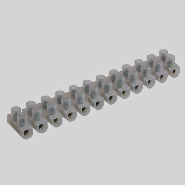
It's known variously as terminal strip, connector strip or connector block. When I started out with this electronicky stuff as a child, these blocks were usually made of dark brown plastic and looked like blocks of chocolate. My dad always called them "chocblock" and he's the guy who taught me electronics so it stuck.
The other term I use is "valve", never "tube". Why? Well, to me the word "valve" suggests what the little glass thing is doing but "tube" just says what it looks like. I guess I prefer process to appearance. And my 1961 copy of the Mullard Maintenance Manual calls them valves. If it was good enough for Mullard, it's good enough for me.
When I talk about "tag board" I mean this stuff...

... and when I talk about "tag strip" I mean this.

There are bound to be other terms and phrases that crop up. If I miss explaining them, or I don't make it clear, use the power of commenting and ask! After all, that's why I set this up as a blog so that we can get some dialogue going.
And don't forget that clicking on any of the pictures opens them up so you can see them better.
Right, the morning so far...

Most of the bits that were in the box had to come out so I could solder the mains socket to the transformer leads.
The transformer I've used has dual primary windings, meaning it can be used for 110/120v or 220/240v simply by connecting the windings either in parallel or series. CBA is going to be used in Australia, so the windings had to be connected in series for the 220/240v option.
Snipped, stripped and soldered...

... then a rubber insulation sleeve added...

... followed by a piece of heat-shrink tubing...

... which was shrunk using an old hairdryer I keep just for that job.

It might look like overkill, but there's going to be half mains voltage appearing on those two bits of wire, so I'd rather be safe than sued.
Next up I had to make some sort of best guess about how much cable to trim to connect to the mains socket. In the end I decided to leave enough length so that the socket could be soldered from the outside of the box, rather than struggle with trying to solder it once it was bolted into place.

And the heat-shrink gets used once again. Not only is it inherently safer, I think it just makes the finished job look a little more professional.

On the inside of the box you should spot that the earth wire (the thick green one on the mains socket) is considerably longer than the live and neutral (the thinner brown and blue wires).

And there's a reason for that. Safety! If, for any reason, the socket gets ripped from the box while the amp is powered up, the earth cable will be the last one to be pulled away from the chassis.
Now we get back to those 6.3v heater cables. Remember earlier in this blog when I talked about my plan for connecting these up using chocblock? Well, time to decide where to mount it. At first, directly over the mains socket looked good.

Then I thought about it some more. It probably wouldn't cause much interference having the heater supply run so close to the safety earth... but why risk it? It's the sort of thing that I might get round to testing at some stage, but not today.

Instead, I positioned the chocblock just above the transformer and to one side of the lid hinge (saved me drilling a hole through it).
And the pic below should give some clue about my thinking for connecting the heater cables when the time comes to screw the chassis to the box.

That's coffee break over. Time to get back in that attic and make a start on putting the pre-amp together. I'm hoping to be in a position to power this thing up in a couple of hours.
No comments:
Post a Comment